Post 23 in a continuing series…
—————-
I took the opportunity to clean up those 9/4 thick, 12" wide boards which came into my hands recently. First off, of course, is jointing:
The Aigner support table, which you can see mounted at the far end of the outfeed, is handy for long and heavy sticks of lumber.
Some readers have expressed concern about my placing pieces of wood on the jointer tables for photography, however these sorts of chunks of wood, around 75 lbs (34kg) each, place far more load on the tables – a load that the machine is completely able to handle without any issue whatsoever.
The chain-sawn stock, as might be expected, did not yield quite as much usable material after clean up as you would get with stock sawn by other means. I think that when all is said and done, the most that 3 of the 4 boards will yield is going to be 1.75" for thickness.
After planing, a little bit of mottling to be seen for sure:
The left hand board (above) has a bit more flatsawn in it than I might like, along with a few small knots. Not sure how I will make use of this stock at this juncture, but it sure is some fine looking material.
I recently picked up an i-Gaging 12" (300mm) DRO for my SCMI planer, and today I tackled the install of that device:
I modified one of the brackets which came with the kit so it could be attached to the existing visual depth gage on the side of the planer’s table:
Before calibrating the readout, I planed some stock and checked dimension:
Then the DRO could be set:
The i-Gaging DRO attaches with a magnet at the back directly to the metal plate behind, and comes with a long connection cord so it was easy to mount on the planer.
Now, some may be wondering why I would want to put a second digital readout on the SCMI planer. Normally one would think one readout should be sufficient. Ah, but it isn’t. This is SCMI. It’s not German.
I have found that the SCMI’s built-in readout is not reliable. Sometimes it jumps settings by just a smidgeon, and when taking a final pass to target dimension you find you have accidentally gone 0.01" under. It’s annoying when that happens. Sometimes the SCMI readout jumps an inch or more out of adjustment. Sometimes it is perfect for weeks on end, and then suddenly it isn’t. I don’t trust it, let’s put it that way. I have learned to run test sticks through before final passes, but that gets a little wasteful after a while, especially in light of the fact that it is a work-around for a defective technology.
That’s not the only shortcoming however. The other defect with the SCMI readout is that to change settings from inch scale to metric, you actually have to remove four screws from the front panel and tilt the entire mounting panel forward so as to gain access to some tiny switches mounted on the back of the unit. A 5-minute job. Not what you would call a well-designed or convenient arrangement. If you’re working within only one measuring system, this would be no issue, however I work in both systems and even when I’m working in one I may occasionally need to produce items, like jig parts, etc., that conform to measures in the other system. The hassle with the SCMI readout in how one changes scale has lefty me simply having to use a pocket calculator and converting inch to mm, or the other way. A little tedious.
With the new DRO, I’m hoping to gain improved accuracy, as the readout is taking data right off the linear scale and the table’s actual height, instead of the stock device which takes data off of an encoder connected to the end of the main drive screw. I will be able to move back and forth between metric and inch as I like. The i-Gaging unit cost about $90.00, which was rather inexpensive if you ask me. We’ll see how it works out over time.
The next order of business joinery-wise was to process the shachi sen, which in this case are parallelogram in section, and tapered both for length and thickness. In the past I’ve formed these compound tapered parts using a combination of router table and hand plane. This time I decided to get the milling machine in on the action, in the hope it might lead to a cleaner and more predictable result. If there’s an avenue to be taken in quest - or promise - of a better result, I’ll take it and see where it leads.
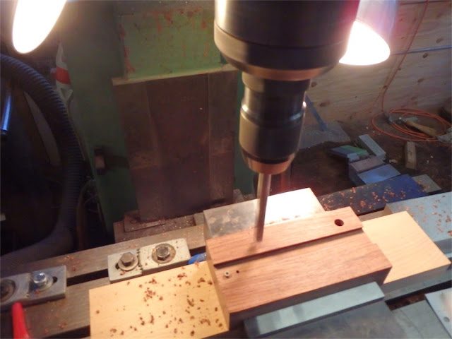
I needed to make a fixture to hold the wedging pin stock for milling work, and this fixture needed to attach to the sine plate. The sine plate comes with 3/8" NC bolt holes, 2" on center. I took the pin fixture, a chunk of bubinga, and milled a groove to hold the shachi sen. Then I marked off the bolt centers on the piece and clamped it into the Kurt vise. I eye-balled the drill center spur to one of those center marks and punched a starter hole through with a 7/16" brad point drill.
Then I used the DRO to move the table exactly 4" over:
And drilled the second hole, exactly 4" from the first:
Then I moved the other axis lead screw to offset 2":
Third hole:
And a final reset for position, heading 4" back the other way to return the DRO to 0.000:
4th of 4 could now be drilled:
Drilling holes on exact centers is one of those woodworking jobs to be tackled with care otherwise, and it usually takes some time to realize clean results. With the milling machine and its DRO however, the task of drilling holes on precise centers is a walk in the park.
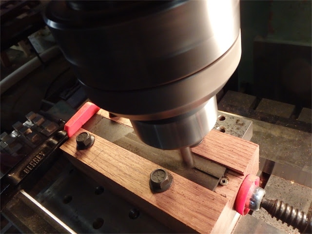
The bubinga fixture was then bolted onto the sine plate and the plate shimmed so as to incline the block with its affixed shachi sen blank. Milling could then commence:
Another view:
A little piece remained in the middle to clean up:
The clamp, and small screw at the other end, is a simple means of keeping the pin from moving while the cutter is engaged.
Here’s the first wedging pin, with one of the faces tapered down about 1/32nd, just a check to see how close it is getting to a fit on the trench:
It was a starter.
After milling one face of each pin, I needed to flip the pins over in the fixture and reset the sine plate, doubling the slope:
Doubling the slope is easy to do as all that is needed is to double the thickness of the shim stack.
Now onto round 2, the sine plate re-angled, and working the other face of the first pin to taper:
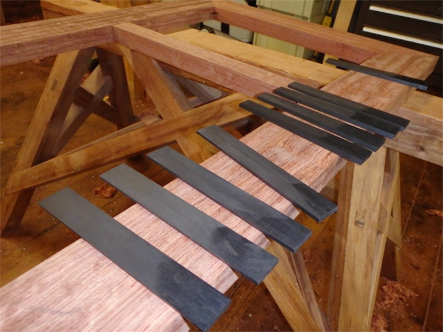
At the end of the day I had all the pins tapered on both sides, but still a hair fat for thickness:
I’ll be tapering them down for width next, and when that fit is getting close to the mark, I’ll revisit the tapering for thickness until I have achieved a crisp fit of the pins into their mortises. They have to fit well on all four faces. If the taper across the width is wrong, the joint won’t draw up properly, and if the taper for thickness is too little the pin won’t fully insert, and if the taper is done too much, the fit will be loose and the pin could crown crosswise when driven in hard. Fitting these is a bit of a dance.
All for today my friends. Hope to see you next time on the Carpentry Way.
via Tumblr http://davidpires578.tumblr.com/post/136721765089


No comments:
Post a Comment