Click here for a the previous post.
——
During the interim in which I constructed and installed the Japanese ceiling, I moved the cabinets along in a couple of minor ways. I have been applying patination to the bifold door hinges, still in progress, and contracted with a local machine shop for the fabrication of hardware for the bifold door main hinging.
One thing did crop up while the woodwork for this cabinet sat, and that is a problem with the four plank shelves, three of which cupped. I guess that’s one advantage of proceeding slowly with a build, you get to see certain outcomes that otherwise would have occurred after the piece had been delivered to the client. Given the choice, I’d much rather the problem occur while the piece was still in my possession of course.
I took precautions, as usual, when dimensioning stock down to make those shelves, jointing and planing over several days, balancing stock removal on both sides of the blank, etc., and after applying 4 or 5 coats of finish to both sides, they were flat. Several weeks go by, and they had moved out of flat to an unacceptable degree. The cause, given that bubinga is generally a decently stable material, particularly when in quartered-to-rift grain orientation, as these shelves were, lays either in how the material was originally dried, or possibly in growth stresses in the tree that were slow to manifest. I tend to think it was mostly attributable to the drying, and therefore I won’t be buying bubinga from that supplier any longer.
It goes to show as well that solid plank construction is going to allow for a greater amount of movement than frame and panel construction. There’s a reason you don’t see much of it in the classic Chinese work. This aspect - the advantage of frame and panel over other methods -has always been quite clear to me, however I had thought that maybe for shelves it would be okay. In fact, making ¾" (19mm) thick shelves at 17.5" width out of single boards might in most circles be considered quite luxurious as a use of material.
No such luck though, so I am fabricating new shelves and these ones will be, you guessed it, frame and panel.
I sliced up the original shelves, jointed and planed them down, so as to form panels:

That took next to no time at all, as they are ‘merely’ quartersawn bubinga.
For the frames, I had but little extra material from which to choose. In fact, all I had was a remnant flatsawn chunk from the middle of the original 16'x 52" x 3" slab that had jump-started this project many moons ago. While I have little use for flatsawn stock generally, by resawing this piece lengthwise I was able to obtain 4 sticks of perfectly quartersawn curly bubinga.
Curly bubinga was a harmonious match for the material used for the two principal horizontal frame and panel assemblies in this cabinet, which lie above and below the shelves themselves, so from that perspective curly bubinga was an excellent choice. What made it a less than scintillating choice however, was the fact that as curly material, normal jointing and planing was only going to get me so close to dimension, lest I risk too much tear out, and that meant that my milling machine was going to be the route for getting to finish dimension.
That meant that basic dimensioning was going to take a couple of days, not 15~20 minutes.
There’s something about having made well-fitted shelves, and then applied many coats of finish to a pleasing result, only to have to start all over again, and to boot be employing a different material and form of construction which was going to add many days of work. I had thought I would be moving into final stages with the door framing - instead I take a step back and work on shelves again. I thought it over long and hard before committing to this course. I was initially a little grumpy about the extra work, however I am more than happy too knowing that the result will be better than previous. And that is what it is all about for me and my woodworking: a continuous striving for improvement.
So, on with the stock prep, day one comprising the resawing, jointing, planing and that left me with decently clean stock, albeit a little tear out here and there:

The stock is sufficiently oversize that the tear out is of no concern.
Then first pass with the milling machine on all the long sides of each of the 16 sticks:

I’m using a CMT top bearing bit with negative rake teeth, which all but ensures zero tear out.

Now working the edges:

In my humble opinion, so long as you are producing chips and not dust, all is good with the world:

After round 1, I had the sticks good and square - you can always get a sense of that by how well they stack next to one another:

Notice on the far right of the pile that there is a defect there. I had to patch that area, as I simply have gone through absolutely all of my curly stock. As with many other stages of this job, i have no spare sticks to work with, so layout and cut-out mistakes must be avoided at all costs.
During the first day of action with the milling machine, cutting left to right to left to right…, I noticed towards the afternoon a certain odd noise start to develop with the machine. This noise grew worse over time and it associated to the power feed. Every time I shifted direction, the noise intensified. I started to get this feeling of dread come over me, akin to the feeling you get when you start to apprehend something is decidedly wrong with the internals of your car’s engine. As anyone with experience knows, you don’t pull an engine out of a car and strip it all apart just to replace a single valve, or pushrod seal, or piston ring. When you take an engine apart, it is generally wise to rebuild the whole thing. It’s cheaper in the long run.
I was worried that the gearbox on my Zimmermann mill was developing problems. That’s sure what it sounded like, and I could see that to get at the gear box was not a simple job, and may even mean stripping the mill down just to get at it. Besides the timing being lousy for this, I am not in a position to have the mill down for long periods, let alone pour money into it.
I didn’t sleep well last night, and was feeling a bit on the mopey side when I went to the shop this morning. I was fearing the worst, but I hoped, with another round of dimensioning to do on the mill that the gearbox would at least do me a favor and hang in there until the task was done.
The next day I started milling, and sure enough the noise was there right away. I couldn’t seemingly wish it away after all.
But this time I got in a little closer with my head to the gearbox to see if I could more precisely localize the sound, and discovered, to my considerable delight, that the noise wasn’t coming from the gearbox after all, but from the motor and pulley drive set up on the outside of the gearbox. I removed some allen cap screws and got the motor cover off, and sure enough I found the culprit: the motor’s drive pulley was coming loose. Whew! That was good news indeed.
Curiously, the square key which ties the pulley and motor output shaft together was absent. I’m not sure if it was missing from previous repair or whether it had simply come out at some point and worked its way past the cover and to the floor (somehow). Whatever the case, a new square key and set screw were needed, so off to the local hardware store I went. Now, the correct size key was 5mm x 5mm, 25mm, however, this is the US after all and selection of metric parts remains less than optimal at most hardware stores. As expected, they had no metric square keys. I was able to find 3/16" (4.76mm) square, 1" (25.4mm) long key stock, so that would have to do in the meantime. Better than nothing.
I fitted the square key and new set screw to the pulley, and put things back in order. It worked, but not silently, and after a while started getting noisy again. I took it apart again and realized that after the old key had fallen out or been lost, and the pulley gradually worked its way loose by grinding the set screw away, that the inner bore of the pulley had been sufficiently worn to now be a poor fit. Correcting the problem, however was, at best, a job for a machine shop. I wasn’t interested in yet another delay however, so I improvised, taking a plastic dado set shim, wrapping it around the motor output shaft, and then slipping the pulley back on over top:

Surprisingly, this worked like a charm! The pulley spins without wobble or any noise, stays put, and all is well.
Now, I’m not the sort who leaves a 'spit and bubblegum’ type of repair, as this one surely is, until it next fails. I’ll be taking that pulley to the machine shop soon enough and get it properly repaired, but for the interim, my mill will be usable and I can get the job done.
Round 2 of milling could then proceed, and a whole lot more quietly I might add. Here, after having worked all the broad long faces, I am gang-cutting the edges of half of the short pieces:


They were done after not too long:

The stock is about as square as can be, and within a few thousands of dimension in every axis. I’m always pleased to obtain results like that - it’s like putting the dart into the bullseye when you actually meant to do so….
The frame stock now prepared, it was time to turn to the joinery work. Options abound for corner joints. I’m going with a form of mitered, tongued, and tenoned corner joint with shachi sen. I last did this variation of that joint on a Walnut Vanity I made about 10 years ago (link), in that case with both a tabletop frame containing a tongued panel, as well as the support frame below it.
I’ve cut this type of joint in myriad ways, and this time I decided to have a go with my mill. I thought it might offer some advantages, although if I had certain (other) tooling on hand, a preferable choice might be to process the joints partly on the shaper’s sliding table. You work with what you got, be it hand tools, or sliding saws, or sliding shapers, or milling machines. I lucky enough to have all of those pieces of gear and decided try the mill this time, and meanwhile dream about what sort of shaper tooling I’d like to acquire sometime down the line….
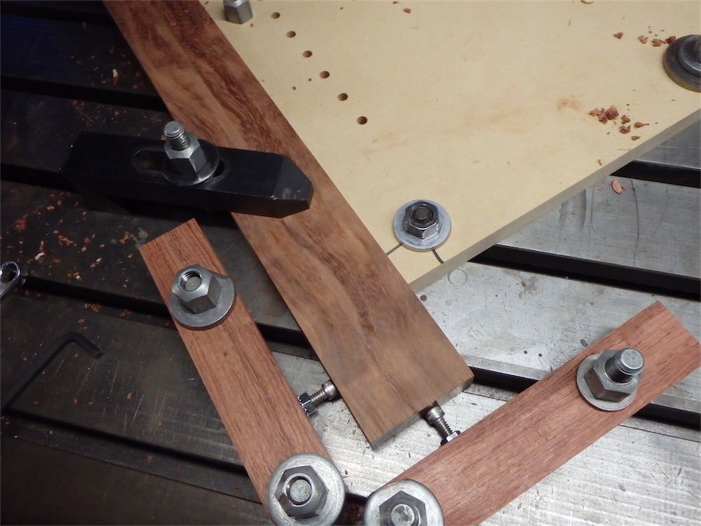
Here’s the jig I came up with on the milling table:

A couple of screw adjusters allow for fine control of position, and the slotted table and beefy hold downs mean that the material is securely held:
So here’s a rough step-by step accounting of how I processed the cuts on the tenoned sticks. First, I ripped the cheeks using a quick-built MDF jig of scraps on the table saw:


That left the following result on both ends of the short sticks:

Then the chop saw, with depth stop engaged, to trim the waste off the miters:

Though both table saw and miter saw could have been used to go to a finial surface with those same cuts, I don’t rely upon those tools for that in this case, I merely rough out with them.
After the chop saw work is done, the mitered tenons are defined, but not yet to their lines:

Then into the mill with the same pieces.
After having taken some time to calibrate the cut on a test stick, and I deck the tenon cheek and trim the mitered shoulder in one set of passes:


The stick is then flipped around to the other side of the jig and the process repeated on the other side, with the slight difference of using a climb cut on the abutment.
Result is a tenon within a few thou of dimension for thickness and with cleanly cut mitered abutments in a common plane:

The process was repeated until both ends of all the short s
via Tumblr http://davidpires578.tumblr.com/post/155831915024
No comments:
Post a Comment