woodwork
via Tumblr http://davidpires578.tumblr.com/post/146910439084
This is the final post depicting the construction of an interior for the East Asian Language department at Colgate University in upstate New York. While this concludes my scope of work, additional plastering and painting are yet to come, and once these are done I’ll share ‘final’ pics here on the Carpentry Way.
The final push took place over a day and a half, with the first day being rather a long one. I work without breaks pretty much, barely stopping to even eat, so by the end of the day I am a bit strung out. I work like that more or less at the shop too, though I will occasionally take a lunch break.
Things went well. The tasks I looked after included:
There were a few minor tasks as well not worth enumerating (or which I have forgotten about already). It was a full slate of work for the time I had.
I didn’t take any ‘in-process’ pics, however Dr. Hirata, the department chair, took loads of video and photos, and at some future point there will be a video produced I’m sure. All I’ve got for now are some pictures of the space as I left it.
The first two are a panorama of the Japanese room:

On the left wall of the picture you can see the kake-shōji. It was supposed to be easy to hang, as I had purchased special fasteners from Lee Valley:

The installation instructions were simple enough: drill a 1/4″ hole in the wall, through the steel stud, and then use a #3 Phillips bit to drive the 1-Shot anchor right in. After that a wood screw can be driven in to the end of the fastener to hang whatever it is you want to hang. I followed the instructions, and when I tried to drive the anchor in, it got partway in and then the thread stripped out. I tried a second brand new fastener in the same hole, and the same result was obtained. I drilled the hole bigger. Same result. Drilled bigger yet. Same result. It simply would not work.
I suspect that the steel studs behind the wall at Colgate are significantly heavier duty than the ones pictured in the Lee Valley product page, but I have no way of knowing.
I had to go to a plan ‘B’, and it was 8:00 at night so there was no opportunity to run to the hardware store. I drilled pilot holes with some self-drilling drywall screws intended for metal studs, and then threaded in a couple of Tapcon anchor screws to those holes, fasteners which are otherwise designed for masonry walls. Those worked perfectly.
On the other wall, you can see the kake-shōji also hung, and that wall is concrete blocks behind the plaster board. Fortunately I had brought 4 of the Tapcon Screws with me, all of which had been slightly modified at my shop to fit in the concealed brass hanger cups epoxied into the backs of the kake-shōji frames:

It’s funny how seemingly minor things can suddenly become big time-consuming dramas sometimes.
An overview of the space through a professor’s office door:

Looking back the other way, showing the wainscot, door casings, and run of nageshi above that:

I suggested that at some point they may wish to consider replacing the doors with something (which I build) that goes better with the new woodwork.
Another view:

Another view:

Obviously the ceiling needs to be tidied up, and some painting work remains. However, some electrical work remains too, so that will be done in the near future and then the paint and plaster can be finished.
I’m pleased with the appearance of the new room, and especially like the shimmer of the figured avodire in view everywhere. There were loads of frustrations in terms of getting the new woodwork to fit against walls which were anything but flat or plumb, or which had square corners. While anything can be solved given enough time and scribing, etc., the constraints of the budget did not allow for this (it would have added at least a week to the job I’m sure) so in the end I simply did the best I could. The other alternative would have been to gut the rooms completely and fix the framing before applying new sheetrock, etc., however, again, budget constraint kept that out of the range of possibility. You have to cut your coat according to your cloth, as they used to say.
One bright spot to be sure was that the adhesive I brought this time actually lived up to its billing: Titebond’s Titegrab. There is none of it in New England for some unknown reason, so I had to obtain it from a Lowes down in Pennsylvania, and have it expedited up to me. An excellent product, though not without a certain learning curve.
All for this round, and all for this project. I hope you enjoyed the account of the build and installation.
After 2018, I’m working on a theory that odd-numbered years are better than even numbered years…..
I have decided, and not recently, as a result of numerous personal quirks and failings, that by and large I am not taking the simplest route, the quickest out, the fastest way from a to b or anything along those lines, particularly when it comes to woodworking . I’d rather realize an ideal that comes out of having taken a good long look at some of the best pieces from antiquity so that I can also ask: what’s the best answer to a given problem, given any constraints that might be present?
I’m not saying I have all the answers to that by any stretch, but am merely an observer and reporter of the scene along the particular lines of investigation that appeal to me. Hopefully some out there might also enjoy what might at best amount to rambling investigations of a joinery nature?
Besides the functional and constructional aspects relating to design, a piece built to last should look good – good enough at least for people to want to keep around for their lifetimes – and hopefully realize an outcome, in terms of ultimate durability, well beyond one or two lifetimes. Designing something to be robust is not so hard, but making a piece robust and yet graceful, not overly thickened in the part dimensions, well, that is an altogether different challenge. How to bottle the genie of ‘timeless design’ is another question.
With the futon cabinet, once I had worked with the client to determine the design direction and the rough sizing of the cabinet, there came the question of how the piece should look. Part of that is the choice of wood, part of that is the decision about how much joinery to express/hide, part of that is the nature of what associates to joined work. Finally, there are molded profiles and chamfers, which contribute greatly to how a piece looks, to play around with. Joined work is not going to look like veneered work most of the time, unless, that is, that the veneered work is making an extra effort in the artistic direction of resembling a joined piece of solid wood. This does happen.
If I am to, er, adhere to that concept of no-glue wood framed construction ever more closely, it means that this piece will be built, if at all possible, entirely with frame and panel work (rather than a corner-joined plank carcase as seen on the sideboard I made for the client last year). That piece combined carcase work with frame and panel elements. This time, I seek to only work with frame and panel elements. There’s one design driver all by itself.
The employment of frame and panel offers the chance to break the piece into discrete framed panel units insofar as possible. The doors are frame and panel units, as is the back of the cabinet. The top and bottom are similarly frame and panel, and then we have the latticed sides, which, though not paneled, are frames infilled with lattice and realize some of the same benefits as a frame and panel.
The biggest difficulty in designing with frame and panel is not so much in making the basic frame and panel units, for those are all much the same in how that are built. The difficulties come, initially, with how one connects the various frame and panel units to one another.
One choice for that is to use posts at each corner which connect the top and bottom frames of the cabinet together. Then the question becomes: how do we connect the posts to the frame and panel assemblies which (may) meet the post upon more than one face?
There are frame and panel units which attach to the post side-to-side, and there are other frame and panel units which will connect to the ends of the post. Each situation is a separate problem in itself, and each offers a limited range of solutions.
What becomes a most critical consideration in regards to the ‘how’ of the joinery, is that of ‘what’ the order of assembly needs to be. Order of assembly must be fully worked and out double checked, as you want to produce a cabinet in the end that can be assembled. I live in terror of being painted, as a self-inflicted injury, into that corner again.
Joining discrete wood frames to one another, or to posts or other intermediary elements, means that many of the connections are of a ‘sistered’ nature. If you want the parts to be closely together without gaps, or, to form a structural connection of some sort, and you want the joinery to be demountable and not involve metal fasteners, then the choices in solid wood joinery come down, as far as I know, to sliding dovetail keys, floating or incorporated in one of the members, or sliding hammerhead keys, or crosswise floating tenons secured with draw-bored pegs.
There are pros and cons to each approach, but one controlling factor is simply the question of how, and in what order, are the parts are to go together.
Sliding joint assembly means the use of dovetails, dovetail keys, or hammerhead keys, and those have characteristically two directions of movement, one in terms of how the parts are offered up to one another, and the second, generally at 90˚ to the first movement, in how the parts slide along one another to lock up the joint.
While those types of connections provide plenty of close lateral connection between the parts, the defect to the sliding connections is that they do not fix the joined assemblies such that they cannot continue to slide against one another from then on out. They might be limited to one direction of movement. And when they slide apart, they also tend towards greater looseness So, if you want the connection to be more rigid then you will have to add something to it to prevent the parts from sliding against one another. Not what you would call an insurmountable challenge, but when you start to pare the part dimensions down some, and things are getting crowded together at a confluence of joinery, say, then it may become less straightforward.
If you employ the floating pegged tenons instead of sliding dovetails then there are consequences as well in terms of assembly directions.
With the issue of joining a post 90˚ (or other angle somewhat close to 90˚) to a frame and panel assembly via the post’s ends, typically means the use of mortise and tenon. Connecting the post’s end to the frame is going to be done either at the corner of the frame where the joints are located, or some distance removed from that.
In this cabinet, the desire to maximize interior room for the overall volume, for one thing, precluded against the posts being setback from the corners of the cabinet to any significant degree, though pushing the pasts back away from the corners does open up options in terms of the joinery to be used, both at the corner and where the post meets the frame.
I needed to accommodate the front doors of the cabinet at the location of the front posts. The door hinging is configured so the doors can swing 270˚ open, and the profiles of the front posts and the hinging stiles of the door are mated closely to one another. I think this arrangement is vastly preferable to having doors which stop in the open position where you end up with the door frame free to run into surrounding support framing as it reaches the limit of its opening. It is the sort of accident which stresses the cabinet joinery and hinges, possibly dents pieces of cabinet woodwork, fails to win the heart and mind of the most ardent client, and the open door remains a continued hazard to walking in any case. Best avoided if you ask me.
In this cabinet, the front posts are to be shaped to accommodate the 270˚ swinging doors, while the rear posts are shaped so as to provide connections for the demountable back panel unit, a piece that normally is not opened or removed. Both posts are expected to connect identically to the top and bottom cabinet frames and maintain symmetrical reveals to those frames.
With the connection between post and top and bottom frame/panel units at the corners, and the top frame molded on its outside face as it is in this cabinet, certain joinery options are thereby manifest, and certain other options are not going to prove suitable. And as noted earlier, the deciding factor of which joint or even constructional system to use depends a lot upon the assembly sequence. It’s like understanding an interlocking stick puzzle, or burr. There’s a certain order to how things go together/come apart and if you don’t pay very close attention to that when you are designing then you could end up in a predicament.
Generally the joint which will work at the top corner is also going to work for the bottom sill frame/panel assembly corner. If I wanted to also keep a consistency in the look of the most exposed-to-view-joinery, then that aspect might be something to which I paid heed, but with the top of this cabinet the post tenon could be through and thereby exposed to view, while on the bottom of the cabinet the tenon end was not going to be visible even if through. So, that gave some leeway in terms of the details of the connections at top and bottom not needing to be the same as one another.
The joint between the post and the upper frame involves a tenon, which, if I were employing glue, could be kept relatively short. Here, with no glue to grip it, it needs to be a bit longer to accommodate some sort of mechanical stopping/locking mechanism. Given that the upper frame and panel unit joins to the post tenon as a pre-assembled component, then tenon, in order to be accessible for mechanical locking, needs to pierce right through the joint.
Now, the tenon could be fox-tailed, a concealed internal one-way wedging of the tenon otherwise known in Japanese as the ‘Hell tenon’. However, I want that demountability between the top framed unit, the post, and the bottom framed unit, so no use of hell tenons seemed worth considering. If demountabiliy was unimportant otherwise, then it would be a connection to consider.
Obviously, even in no-glue construction one could make exceptions for impermanent bonding agents, like a weak starch glue of some kind, or some wiped-on lacquer, to lightly reinforce a connection, which otherwise is fully dependent upon a tight fit between mortise(s) and tenon(s).
On the top frame of this cabinet the joint is fully exposed to view, while on the bottom frame it will be completely hidden. This difference leads to the possibility of different outcomes in joint design for those two places.
On the top, I choose to show the top of the tenon, but it is neither wedged nor is it reinforced with a weak glue. How then is the top frame and panel assembly prevented from being pulled apart from the post, you might wonder? Just m&t friction?
My solution was to make it a good friction fit joint, yes, and to also employ the side frames as an intermediary connection between the posts and the top frame. The side frames with lattice connect to the top frame’s end pieces with sliding dovetail keys, and the side frames are also connected to the posts with sliding dovetail keys. What prevents the connection to top frame from continuing to slide after assembly is that the flanking posts tenon into the same frame member. That blocks the side to side movement. The up and down sliding of the joint between lattice frame and post is blocked by way of a pair of wooden tapered pins.
The assembly sequence is therefore one of connecting side panels to the top frame end members, and then connect the posts to the side frames and slide the posts along the lattice frame until their top tenons pierce through the top frame’s corner joints.
For the bottom frame connection to the post, the only condition which is different, as previously mentioned, is that the post tenon which pierces the frame corner joint emerges completely out of view under the cabinet. So, I do have the option there of making a direct mechanical wooden connection, instead of borrowing the connection form that I did with the join to upper frame corner. Moreover, I am needing to do a direct locking connection to the tenon as a result of the previous decision about how the cabinet parts assemble to one another starting at the top. Once the posts have slid into place in the top frame, sistered to the side panels with lattice, then the option is no longer there to do a similar connection with the bottom frame end pieces and the bottom of the side frame as I had done on the top of the post.
If the cabinet bottom was the last frame and panel assembly, then the post tenon would need to either be trimmed flush with the bottom face of the frame member where it emerges, or some point short of that face.
If, however, the bottom frame and panel is not the bottom of the cabinet, if there are feet or some sort of sill assembly that raise it up off the floor, then other options arise for the post tenon joinery. The most obvious of these being that the post tenon can be elongated well beyond the face where it emerges, and is wedged crosswise. This approach is also preferred generally by me as it is a demountable connection. So, that’s the direction I tried to develop here.
This design direction initially did not come from trying to solve a joinery issue – I thought the cabinet should be a little bit more than the bare minimum of a simple box, and thought it would look better with some sort of plinth or base below the bottom frame, something to set the box on a pedestal.
Initially, I drew the cabinet with a supporting 4-sided skirt of sorts which joined at the corners with a miter:

The skirt had a surface which was concave, beaded, and which featured a surface jogging both inward and upward. One thing that could be said about it is that it was not going to be an easy component to make.
When it came to resolving the design details at the cabinet corners however, I tried a variety of approaches to satisfy the aesthetic desired. And yeah, it can be done in various ways. But, I wasn’t quite satisfied with any of the solutions I arrived at technically, especially when it came to figuring out how to terminate the pesky post tenon connection behind/into the skirt/sill and tied up in this puzzle was also the issue of how to attach the skirt itself to the cabinet’s bottom frame and panel assembly.
At one point, in working to solve this cluster of challenges, I redesigned the skirt so as to be composed not of four sticks joined with miters at the corners, but of four pre-assembled ‘miter corner units’ and 4 interconnecting stretchers between those corner units. This is an overall increase from 4 parts to 16 parts for the sill/skirt though.
This different construction gave the corners more of a look, it seems to me, of being upon pedestals:

The inner returns on the skirt could be made to curve inwards instead of outwards as they are shown above, and the pedestal look for the area would be replaced by a look of 4 squat sorta feet poking out.
Here’s a look at the underside of one of those pedestals, or corner units:

The triangular plate stiffens the corner and attaches to the corner with a tongue and groove. There are 2 floating tenons between the corner of the skirt and the lower frame corner as well to reinforce it. It was a workable solution but it still left me feeling like I hadn’t quite solved the problem yet, and I found some of the joinery on the awkward side. Despite the reinforcing steps, I also was left with the niggling feeling that the joints overall had a degree of fragility which led me to realize that I wasn’t quite done yet with the design.
I didn’t like the recourse to gluing of the corner miter, regardless of what sort of join w
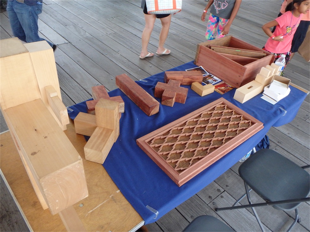
I spent 10~5 yesterday on the boardwalk in front of the Boston Children’s Museum with a table presenting samples of Japanese joinery and my woodwork, most of which could easily be assembled and disassembled by small children. Here’s a snap of my table:
Design work on the remodel of the Colgate East Asian Language Laboratory is getting closer to the finish line. I thought I’d share some sketches I’ve come up with for the space, though keep in mind this is not completely finalized as of yet.
The space consists of a pair of small rooms linked by a hallway, and along the hallway are faculty offices. The first space I worked on was the Japanese room, occupying a relatively small niche of space. From the hallway, the entry to the space is indicated by a small hanging panel, reminiscent of a ranma:


With the benches out of the way, I have a couple of items to finish up for the Japanese room before turning to the Chinese room and its woodwork.
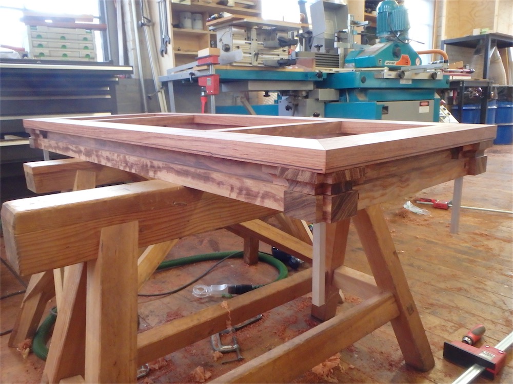
One task that presented itself was to create the crossbeam which supports the alcove post, toko-bashira, and serves double duty as the upper sliding track, or kamo-i for a pair of sliding doors below. For those door, a sill, or shiki-i, also needed to be fabricated.
I cannot obtain avodire, at least not in the US, in the thickness required, so laminated some pieces together:


My wife and I took the opportunity to take a week’s break and head on down to slightly warmer climes. As with any trip like this, we took in some historic homes and I thought I’d share an account here of the interesting things which we came upon. Our tour took us down through Connecticut and New York, circling out and around NYC, and down through New Jersey to Baltimore, Maryland. Though we had the idea in mind that the further south we went the warmer the weather would become, in fact we found ourselves in a heavy snowstorm when we crossed into Maryland.
In Maryland we visited with some of my wife’s relatives, and then the next day headed further south, first into Virginia, and then down to North Carolina. It was nice to see the trees in leaf and flower after the winter. I also found that pretty much everyone I came across in the south exhibited a pleasant mix of politeness and friendliness. It’s so nice!
I’ll detail some of the places we came across below, in the order we visited.
————–
Monticello.
I have been long interested in visiting the home of Thomas Jefferson. He was an owner/builder, though I would use the term ‘builder’ loosely since he did not do any of the actual construction himself but rather was the principal architect. Of course, people often say so-and-so built something when they did none of the actual construction. It’s a curious thing. A lot of the construction occurred while Jefferson was away from the house, as he spent some 40 years away from Monticello after starting work upon it when he was in his early twenties. He inherited the 1500 hundred acre estate when he turned 21. Not a bad start in life I suppose. He also inherited his father’s debts as part of the package.
Jefferson’s Monticello, as a national historic site, was striking to me for one reason more than any other: how polished and slickly run the entire place was. At the bottom of the hill is a newish visitor center with cafe and gift shop, and a shuttle bus takes groups up to the house every 15 minutes or so. and all the staff were so friendly! The grounds are well kept.
Once at the top, the shuttle lets you off near the front of the house:


“Another incident took place on the same occasion, which will further delineate Mr. Hamilton’s political principles. The room being hung around with a collection of the portraits of remarkable men, among them were those of Bacon, Newton and Locke, Hamilton asked me who they were. I told him they were my trinity of the three greatest men the world had ever produced, naming them. He paused for some time: "the greatest man,” said he, “that ever lived, was Julius Caesar.” Mr. Adams was honest as a politician, as well as a man; Hamilton honest as a man, but, as a politician, believing in the necessity of either force or corruption to govern men.“Interesting that Hamilton favored a dictator as the 'greatest man who ever lived’, not an enlightenment figure. Hmm, not sure I care much for Hamilton. Not my cup of tea.


Well, though this video covers ground already detailed in the last two posts, being at last edited and narrated, it seemed worth sharing:
I did my first trip out to Colgate this past few days to install some woodwork. I got into ‘worker bee’ mode while there and didn’t take a lot of photos, but I hope a few is better than nothing.
Here, in the Japanese room, I’ve mocked up the arrangement of the wainscot panel with some plant-on inside corner posts, and a piece of baseboard:

There’s a 2-piece cap to be fitted to the baseboard yet of course.
I’m using 1/4″ (actually measures 0.2″) plywood with one side faced with VG fir. I hesitated to employ plywood, but it was the best option it seemed to me for an appliqué which needs to be thin, and given the difficulty/expense of obtaining VG fir at this time. As you can see, the bamboo floor laminate has been installed in that room and the upper portion of wall has been painted.
My main task in the Japanese room was fitting the various plant-on posts – here’s a look at another area of the same room:

Excuse the dust spots on the lens. The posts, now that they have been trimmed to length, were taken back to my shop afterward, to have yet more cut out done upon them.
The Chinese space at the other end of the connecting hallway saw the installation of the framed bump-out which in turn will later receive a cusped window:

The framing had been largely done in my shop ahead of time, save for final length. I used 2×6 spruce studs, and sheetrock. Not materials I would normally want to use, but they make sense when you are affixing to that same sort of wall system, though the existing framing uses steel studs not wood. I put some drywall compound on the exposed screw holes, and will leave the rest of that work to Colgate’s plastering/painting workers.
Speaking of attaching the framing, I had brought some Spax screws with me for the task, which are advertised on the box as being for various materials, including steel, however I only had luck getting them into the steel framing studs at the bottom of the wall. Of course, when I was atop a ladder and struggling to get the screws in, they stubbornly refused to do their job. I ended up having to go out to a building supply and obtain some self-drilling drywall screws. That really was the only hiccup during this install.
Leaving the site work for the moment, as regards the cusped window, it is made. I elected to use a chunk of bubinga that I had for that. The sides of the frame were made with a pair of pieces joined at a slight mitre angle, with a glued spline joint inside. Here’s my glue-up fixture for that task:

A pair of wedges at each end pushed the two segments together. It worked well.
Once the gluing was done, the parts were marked out in preparation for band-sawing to shape:

Here’s a look at the cusped window frame about halfway along the course of fabrication:

Not yet fitted in the above photo is the face frame portion, now glued on, which gives it the final appearance at the front. That’s almost done, not photographed though, and into its third coat of finish. Also completed is a framed glass panel that attaches to the back of the window via 4 magnets. a sliding panel goes behind that. I’ll install the window frame and associated parts into the opening on my next trip out to Colgate.
Also installed during the visit was the transom at the entrance to the Chinese room, which went in with a little planing and coaxing:

I did end up scratching the wall on the right and some fresh paint was removed, however there will be a bunch of electrical work done in that space and the adjacent hallway, involving cutting into the sheetrock in several places, so further plastering and painting is needed in the space regardless. I felt like I should have left a little apology note for the painters though!
I now have a slate of tasks for the next two weeks before the second installation visit. Hopefully I can complete everything in that timeframe.
Thanks for coming by the Carpentry Way.
Post 25, not even half way there yet in this series.
——————
Now working on the connection between the cornice rail assembly and the inverted ’T’ form beam assembly. There the parts connect with a tongue and groove, the groove having sloped abutments which are chopped out by chisel.
The dado is cut largely by router: