Post 25, not even half way there yet in this series.
——————
Now working on the connection between the cornice rail assembly and the inverted ’T’ form beam assembly. There the parts connect with a tongue and groove, the groove having sloped abutments which are chopped out by chisel.
The dado is cut largely by router:

Lots of time spent kneeling on the floor and sliding around. That’s why they call it ‘knuckle dragging’.
I’ll jump ahead a little to show the result of the tongue and groove joints reaching completion with this first set of parts:
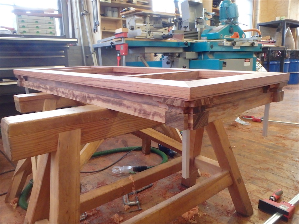
A closer look at one corner:

A flipped-over view:

The Sharpie lines on the edge of the cornice sticks indicate where the molded profile will be taken (later on).
A look at the interface between the two assemblies, where the hope is (after all the parts are together) that I can convince the viewer (who would have to get real close and personal with the parts to check the seams) that these two items are all of one piece:

Another view:

Working now on fitting together the two assemblies for the other cabinet- the dadoes have been cut on the underside of the cornice pieces and I’m ready to try the fit:

The pillow block pairs also require a little additional tuning in this round of fitting, their location guided by aluminum locating pins which were also machined to specific dimensions:

Together, and aligned:

Assembly of cornice to inverted ’T’ beams is now complete for the second set of parts:

Another view:

These two assemblies were then set to one side - banished to Waddie land as it were:

Another view:

To mix things up a bit, I decided to carry on with a bit of red bronze machining before I tackled any more woodwork.
Here, I’m checking to see that I have reached target dimension, 1.000", for the length of the 'tenon’:

I found I was able to complete the milling work on the 1"x1"x1’ tenons a bit faster than I had expected:

It’s nice to have some spares, as screw ups remain always a possibility when there are some many steps involved.
Another view:

I took the opportunity to then dress the bottoms of the leveler feet, though these will not actually be the finished surfaces:

The sharp end of the stick, as they say:

Bronze - this type of bronze at least - doesn’t seem to bad to work at all.
The legs slope at a compound angle, so the feet will also need to be milled eventually at a compound angle - an 'entertaining’ bit of work that I shall be content to visualize for the time being. For now, dressing the bottom of the feet to a flat surface makes for more predictable work in the steps immediately downstream. At least that’s what I tell myself as they fit the straight jacket….
The feet can now be set aside. I milled the legs down 0.1" in dimension, and tomorrow I’ll fabricate a jig to allow me to mortise the leg ends to accept the tenons from the bronze feet.
All for today, thanks for visiting the Carpentry Way. Comments always welcome.
via Tumblr http://davidpires578.tumblr.com/post/137187042934
No comments:
Post a Comment