Post 18 in a continuing series….
———————-
I have obtained an operation manual along with electrical diagram for the Zimmerman FZ-5V pattern milling machine:

Compared to Chinese, Japanese, or 19th century French, the German translation chore has been relatively straightforward, especially as I am able to cross-reference the text with provided illustrations. One word that held me up a while was ‘konsole’, which, unsurprisingly, translates as 'console’, however that meaning is completely erroneous in this case. The Germans use the term 'konsole’ when they are referring to the part of the vertical mill we call the 'knee’. Anyway, I’ve been able to figure out a few things about my machine since translating various sections of the manual, so all is good.
Work has continued on fitting the pillow block assemblies to the inverted ’T’ beam assembly. Here’s one corner, and as you can see the camera was inadvertently set in one of it’s fancy 'modes’:

I used a 0.5" square gauge block to locate the pillow block mortise so as to be directly above the corresponding mortise in the beam corner joint. I thought it would be a good idea to employ a similar guide 'pin’ at each junction, however I only had the one gauge block in that size. So, I picked up some 0.5" sections of aluminum extrusion for this purpose. These extrusions, however, turned out to be only approximately 0.5":

Well, 0.060" out of spec is simply too much. These won’t fit in the mortises I have cut and I’m not planning to make the mortises bigger to accommodate the oversize aluminum pins.
So, a little attention on the mill was required, using a router bit:
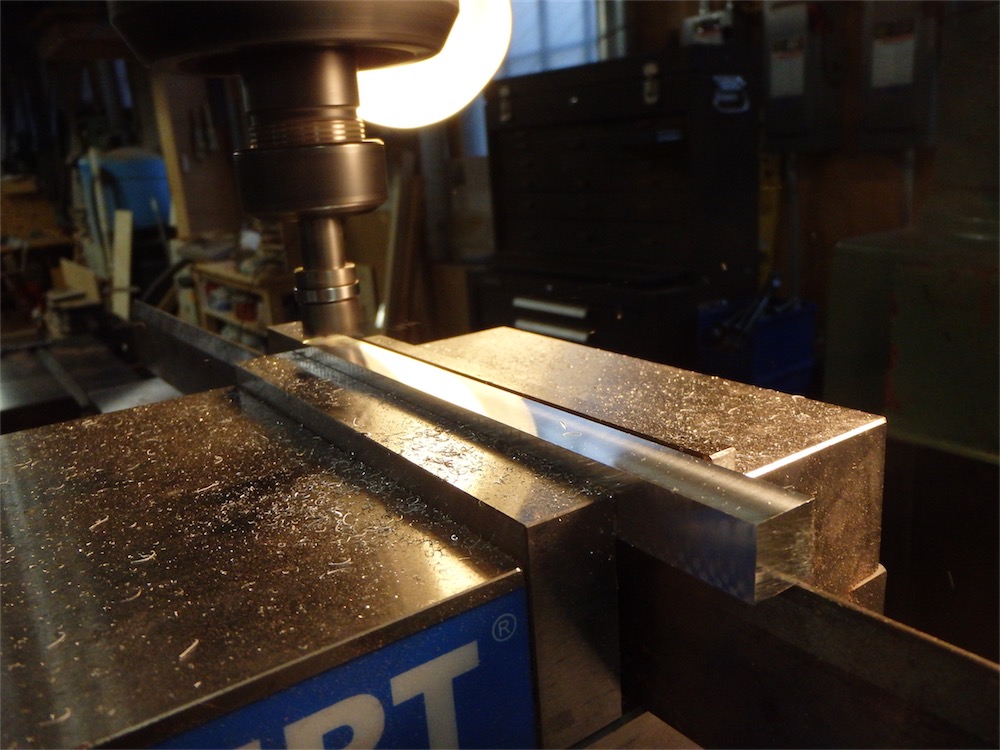
Result:

It’s handy to have a mill.
Another area needing some adjusting was the the ends of some of the raised ribs:

As I always get asked about this, the 'wet’ area you see has been sprayed with camellia oil, which lubricates the cut, which leads to a clean surface and in turn preserves the chisel edge a little longer:

Besides the work on cleaning up the mortises, the raised rib sidewalls of the beams needed to be brought down to size using the LN scraping plane I had bought specifically for the task. The blade looked ready-ish out of the box, however upon use didn’t exactly light my fire. It just made dust mostly. I fiddled around a bit, but in the end found the only way to get the plane to work well in curly bubinga was to roll a hook on the edge after sharpening.
The LN blade, though thick for a western plane, was seriously thin by Japanese standards, and the bevel angle was 45˚, giving a very small registration surface on the stone. Plus the blade itself was in a ’T’ shape - -this confluence of factors made it quite hard to register the blade properly and consistently against the sharpening stone. For the first time in years and years, I made use of a sharpening jig to set the bevel. It did the job fine, but I am not likely to make a habit of using the jig otherwise, as freehand generally suffices just fine with Japanese tools. I took the blade grind to about #3000 grit, and that’s all, as the edge is subject to scraping abuse and there’s really no point working to a thinner edge. After the bevel was set, I clamped the blade between a couple of soft jaws in a vise and used a burnisher to turn a hook.
With the blade set up, the tool takes nice type II shavings:


The plane’s handles can tilt so you can adjust the working position:

It’s convenient to be able to tilt the handles, however I found that even after tightening the fixing screws down a good amount, the handles were still able to move a little bit.
This plane blade is canted forward, I would estimate some 15˚ or so from vertical:

It did the job:

It seems to me that the steel of the scraping plane blade has to be softer than a normal plane blade so as to make turning a hook a possibility. The end result is that shavings can be taken, and a good surface produced, but the blade’s edge does not last very long. I found that could get one face’s worth of passes on a long side inverted ’T’ beam before I had to resharpen. In order to process all the faces on one inverted ’T’ beam assembly - just the raised rib portions I mean - I had to resharpen 6 times. It was an opportunity to work on patience.
After hours of futzing about, one assembly was complete, aluminum gage 'pins’ fitted to each corner to confirm alignment:

A view of a set of pillow blocks fitted to a corner:

Another corner:

The gage pins in turn allowed me to check whether I’d hit my targets. The distance from the outside of one pin to another was 18.5", which works out to 469.90mm:

Unfortunately I had a bit of glare in the above photo, so please take my word for it that the dimension measured was in fact exactly 469.90mm.
Here’s the other end, also pretty much right on the money:

It was satisfying to have the assembled pieces come out exactly to desired dimension where it counted the most. I’ve been extra fussy about this step because the legs are compound splayed and little discrepancies here and there from the correct dimensions have a way of adding up to significant problems when you try and put things together. This has been my experience in the past with compound splayed post structures.
At this juncture I’m about halfway through the above-shown process with the other inverted ’T’ assembly. All the mortises are trimmed out. Just another four rounds of sharpening and scraping to go and I should have the beams done and all the parts together. Then it will be onto the cap beams, which will have locking miter joints.
All for today- thanks for visiting!
via Tumblr http://davidpires578.tumblr.com/post/135292670309
No comments:
Post a Comment