Post 20 in a continuing series….
—————
Work continues on the set of beams comprising the cornice of the support stand.
These beams will join to one another with locking miter joints, and I tackled the miter cutting this time using the Wadkin dimension saw. This is a saw which was designed from the get-go to be configured for the convenient cutting of polygon miters, however in working through the process of cutting miters on these cornice pieces, I became aware of some shortcomings in the Wadkin’s design.
The miter fence affixed to the sliding table, when set in its normal position, makes use of an etched protractor in the table surface, along with a sprung detent pin in the fence which fits into holes in the table top, a separate hole position being provided for the most common polygons. Of course there is a position provided for a regular 45˚miter cut, and if i were cutting the miter cut right through the stick, then this would suffice. However, when there is a tenon in the middle, one has to cut the miter from each face, and the same setting of miter fence cannot be used for both cuts. Ideally there would be a secondary miter fence, called a ‘back miter’ fence, fitted to the saw, and the back miter fence would be set to 135˚. The relation between primary miter fence and back miter fence would therefore be 90˚.
I don’t have a back miter fence. They’re a somewhat rare accessory, and now that I have had a chance to work a few miter cuts on the sliding table of the Wadkin, I am no longer thinking that a back miter fence is something I want to have any more.
Why not? Well, take a look at the set up when there is a back miter fence fitted:

Image is of a restored Wadkin PK saw, part of the Wadkin 'Temple’ up in Ontario.
Notice how, in the above arrangement how the back miter fence really doesn’t leave a whole lot of table surface for supporting the stick which is to be miter cut? That’s a drawback, it seems to me, with the back miter. It would be fine if the sticks you were cutting were only 24" or less in length, but with longer sticks the majority of the material is going to be hanging out in space and that is an invitation for cut out error or mishap.
It seems to me that it would be a better arrangement to put the miter fence and back miter fence assembly together in the middle of the table for most purposes, as that would at least provide equal amounts of table support for cutting a stick against either fence. Why, something like this, an Altendorf Duplex Miter, would possibly be ideal for the same purposes:

Well, I don’t have one of those. I’d like to get a look at one and see if it could be fitted to my saw somehow, or loosely copied in some manner.
I realized early on in mulling over options and in the subsequent fiddling about with setting up the saw for the miter cutting, that it would make sense to place the miter fence in the 135˚ position and work my way from there to the 45˚ position. You’ll see what I mean as I go through the process.
With the fence in the 135˚ position (there is no table setting position for that angle unfortunately, so it is a matter of setting by eye and tightening down the fixing bolt), I took two pieces of scrap, jointed and planed them, and made a miter cut on each:

The two pieces were then placed against one another to see if a 90˚ angle resulted:

A 90˚ angle could only result if both cuts were exactly 45˚.
After the initial set up, test cut #1 yielded a result very close to the mark, and a clean miter line:

With the square held tightly however to one stick, a slight gap could be detected down at the end of the adjoining piece:

The fence was then to be adjusted and test cuts made again until the result was a 90˚ corner between pieces. This process was accomplished by setting up a stop block against the fence to start:

In the above photo, the block was set and then the fence swung open a little to create a gap against the ned of the block.
Then a shim was added between the block and the fence so as to move the fence open slightly:

The initial shim I picked was 0.006":

0.006" proved to be too much, and in the end I found a 0.002" shim bumped the fence over the right amount:

Funny how people say that such tolerances as numbers in the thousandths of an inch are beyond what is needed for woodworking. I find the opposite is true.
With the 135˚ angle set, I used my large Mitutoyo precision square to establish a secondary fence oriented 90˚ to the first:

Around the same time I also took the opportunity to raise the blade and confirm that the saw blade was making the miter cut square to the face of the stick:

This jig referenced the cuts for length using a stop block for each position. I was able to make test cuts, halfway up the face of the miter, then flipping the stick for a second cut, and checking to see if the two cuts were co-planer. It was a matter of adjusting one or both stop blocks until I had the cut length the same on each side of the miter.
With the longer sticks, the process was repeated, however I had to add fence extensions so as to have the stop blocks located far enough to the rear:

The above picture clearly shows how this saw is best suited for cutting short pieces of wood. It’s a bit odd though, I mean, it’s not as if as if only short pieces of wood might need miter cutting. What were they thinking exactly, design-wise? I must be missing something.
I really need, I think, some sort of outrigger arrangement to carry longer pieces for cross cutting. Wadkin made an accessory for the saw which accomplished that, however I am considering whether I could fabricate something do accomplish the same end result. It will be something to explore when I’m not in the middle of building cabinets.
I didn’t find absolute consistency was realized in my approach to cutting miters on the table saw, so I left the miters slightly fat of the lines and will pare them to fit later on. I would rather that the miters came out perfect right off the saw, but not this time. Some of the inaccuracy may accrue to the table itself, which is significantly bowed along its length.
With the miter shoulders cut, I used the bandsaw to remove the cheek portion and then cleaned up a face of the tenon on the router table. The next step was to mortise, and I brought the hollow chisel machine into action:
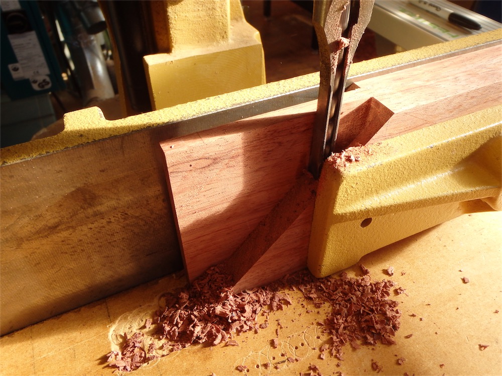
The mortising chisel is not quite long enough to plunge the full depth of the required cut, but got decently close.
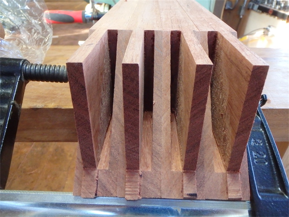
The short ends all roughly mortised:

In the above photo you can also see that the tenon length has been trimmed back as well.
I took the short end pieces and ganged them, then clamped on some paring blocks, one on each end:

I was able to place the blocks with great accuracy using a digital caliper for spacing them apart, and that allowed me to put the mortise end walls within a few thou of where they needed to be.
After the end walls were trimmed down, I worked the long grain sides of each mortise, like so:

This set is done:
Next step was to dress the other tenon cheek, which required an offset fence on my router table:

The offset fence allowed me to clean up the tenon cheek right close to the shoulder without fear of gouging into the shoulder with the cutter.
I brought the tenon thickness down to the mark, and checked the tenon/mortise fits of the short pieces to one another like so:

Of course, the short pieces actually connect to long pairs of beams, however those long beams are not through cut out yet to the same stage. Gotta leave something for tomorrow I guess.
Another look at one of these joints - they are only about halfway done at this point:

All for now my friends. See you next time.
via Tumblr http://davidpires578.tumblr.com/post/135602222964
No comments:
Post a Comment