Post 30 in a continuing series…
———————
While the posts connect to the long side inverted ’T’ beams by way of a tiny 5mm square peg, the beams themselves connect through to the above-mounted cornice assembly directly, using hammer-headed draw bars. I had previously mortised for these drawbars and their associated fixing pins only on the short side inverted ’T’ beams, however I realized it would be better to double those connections up at each corner- thus the long side inverted ’T’ beams needed to be mortised for both draw bar and fixing pin:

You can just see in the above photo that the fixing pin mortise has been filled with a sacrificial piece to preclude blowout when mortising cross-wise for the draw bar.
The sacrificial pins were tapped out afterwards using a metal drift pin:

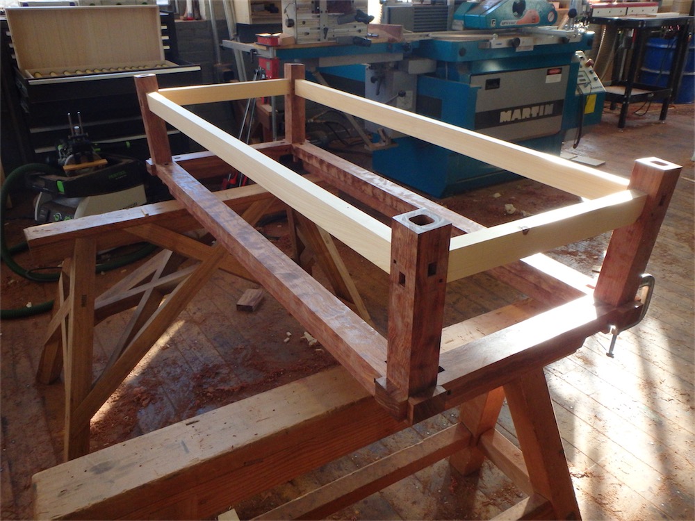
Setting the inverted ’T’ beams aside, at last I can deal with the stretchers. I decided it would be prudent to make up some pieces to gauge the spacing for the stretchers, since, after so many cut out steps, it was likely that there would not be perfect fidelity to the layout established in the drawings.
Here, the legs have been clamped down tight and the test pieces fitted:

As it turns out, the lengths were very close to the target numbers, as were the bevels, save for one corner which was slightly out for some reason.
As the posts slope both ways, none of the cut lines on the stretcher shoulders are 90˚. With the bevel on the broad face of the stretcher the angle is all too apparent, however on the narrower edge of the same stick the cut angle is only at hair off of 90˚, at all of 89. 85˚ or so:

This splay-posted structure is one of the more complicated ones I have done, simply due to the fact that the splay is so slight that many of the angles are just very slightly off of what they would be if the posts did not slope at all.
Another view:
The following picture shows well, I think, that even though the angle of 89.85/0.15˚ is a very slight slope, it counts for something. The bevel gauge is flipped around to show double the effective angle, relative to the fence:

Now working on the tenon cuts on the long stretchers:

To cut each tenon, 4 separate set ups are required:

This one is about halfway along:

The larger bandsaw was used to rip the tenon waste:

After roughing out, the tenons on the long pieces looked like this:

Then on to the router table to clean up the surfaces and bring them to dimension. The cuts off the bandsaw are fairly close to the line, so the amount of router work is minimal, which is the way router bits cut the best:

After routing:

Then, working again on the short stretchers, a second check to see that I am in the ballpark for length, shoulder to shoulder:

The tenons are then further cleaned up, and slight adjustments made, using various chisels:

This tenon is complete:

After the tenons are done, then they must be fitted to their mortises, which seems to take a while. Here, first short side stretcher is fitted up:

A closer look at one shoulder:

And the other:

Maybe a closer look wouldn’t hurt:

On the exit face:

A while later, the second short stretcher was fitted:

Then it was time to work on the long stretchers again - here, I’m checking the shoulder-to-shoulder lengths before final clean up:

The parts can hang in place simply by friction on the side shoulders.
I cleaned up the tenons on those two long stretchers, and that is as far as I got today. The remainder of the stretchers could be fitted up tomorrow, however perhaps my optimism is premature in that regard. They’ll be done when they’re done.
Thanks so much for dropping by and checking out the comings and goings here. I hope you’ll return for the next installment.
via Tumblr http://davidpires578.tumblr.com/post/138635909329
No comments:
Post a Comment