Post 32 in a series….
——————-
Stand #2 is now complete to the same point as the first stand:

One of the pillow blocks for that unit in place:

These two stands have certainly absorbed a fair amount of time, and they’re not done yet:

I’ve been working on the drawing as well, and one thing that was remaining uncertain as a result was how the bubinga and shedua will actually look together. The wood samples I imported to Sketchup all seem to have more of a greenish cast than a brownish cast, and, well, it looked a bit odd as it was represented in the drawing.
I have no prior experience with shedua. I decided that today I needed to get better acquainted, and really see how the stock looked:
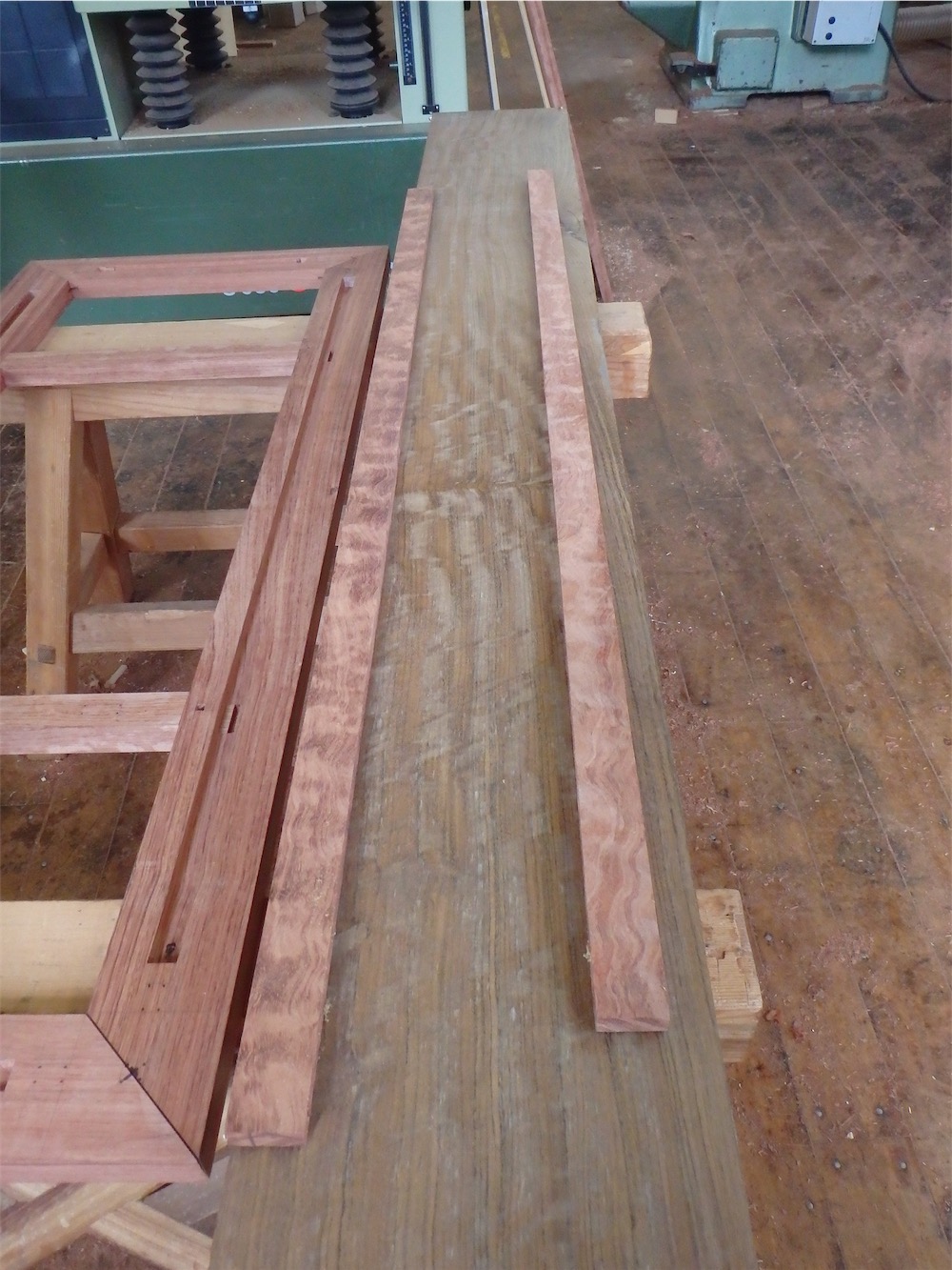
I like the two together., The above photos are in fluorescent light as well, which isn’t especially helpful.
Another view:

The shedua will be used for the 9 drawer fronts of the cabinet as well as a back panel on the upper sliding doors.
It seemed like it was time to re-saw some stock, to see what I really had:

The reveal:

This was getting better by the moment:

I have some nice quartersawn drawer front stock here:

More than the ideal grain orientation however, I really was blown away by the incredible figure this material has - it’s curly and mottled:

I find it mesmerizing. Wow!
Back to those stands….
Here I’m working on the little housings on the cornice pieces to fit the post tenon tops:

Cross-cut, to be followed by a little chisel work:

When in place you can see how the post tenon top pops into the housing:

At this point the tenon tops were found to be a hair too long, and were trimmed down some, ending up slightly recessed from the mortise end wall.
A while later the two long side cornice rails were fitted to the stand:

At this juncture there was some mortising work to do in order to accommodate the drawbar mechanism I have come up with to lock all the frame horizontals together tight. Each corner gets two drawbars, so there are eight altogether. It should be plenty sufficient to keep things together for the duration, and they are demountable as well.
I mentioned several posts back that I had fitted the SCM planer with an i-gaging digital readout as I had lost faith in the factory unit. After install, the new readout was pre-set to be the same setting as the factory readout. I’ve left the two digital readouts alone since then. The planer table has been up and down, I don’t know, a couple of dozen times, thirty times - and here we can see how well they concord:

The one which is correct is the i-gaging, confirmed by planing and measuring the board with a caliper.
This outcome, with the factory indicator being off by 0.01", was exactly as had happened previously. I would send something through the planer, set to a desired setting, and then find the stock had been planed 0.01" undersize. It’s not something I am particularly fond of - it may not seem like much, but add in finish planing work on the piece and it becomes more undersize. It makes for headaches sometimes in later layout and fitting steps.
I’ve have been happy so far with the continued reliability of the i-gaging unit. Nice to have something I can count on.
Back to the work on the stands….
After fitting the long cornice piece, each of the draw bar mortises was checked using a slightly undersize gaging stick:

After confirming the through-mortises for the drawbars lined up, through all the layers, I plunged ahead with the profiling of the cornice piece on the shaper. The resulting profile:

I should have the cornices fitted to both frames after another day.
Thanks for visiting the Carpentry Way.
via Tumblr http://davidpires578.tumblr.com/post/139021392684
No comments:
Post a Comment