The drawers needed some further minor work - trimming the rear floor edges, a process which began on the sliding saw:

A piece of MDF locates the drawer position for the cut and protects the lower arris from blow out when sawing.
The saw cut is then cleaned up by plane:

The drawers have been completed, to the dry-assembly stage, and fitted to both cabinets:

Another view:

Another view:

Next up in the task list are the adjustable height shelves for the cabinets. Originally, I had planned on a pair of shelves each side, however upon further consideration I decided that one shelf each side made more sense, given the depth of the shelves. I decided to set up provision for 7 heights for each of the shelves.
Drilling holes for shelf pins seems like it might be one of those those mundane, low-hanging fruit sort of tasks. In some respects that is true, as, well, how hard is it to drill a bunch of holes? However, each shelf sits on fours pins and if one of those holes is mispositioned, the shelf won’t sit flat upon the pins. If a hole is drilled at a cock-eyed angle, the pin will not sit flat to the surface or support the shelf properly. Those outcomes are not the end of the world, as compensations can be made afterwards, however it seems better, to my way of thinking, to put the holes in the right x-y-z position and correct alignment, from the get-go. The shelf sitting goes a lot smoother afterwards. Drilling holes in precise positions however is not always a simple task in the world of woodworking. At least I have not found it so until very recently.
Now, there are various commercially produced jigs for drilling precision holes for shelf pins. I don’t have any of those, but some look quite decent to be sure. It seems though that, unless one makes a fairly standard sort of furniture piece in terms of its adjustable shelve positioning, then the highly varied nature of the beast makes it a bit difficult for a general-purpose jig to suffice for all conditions. So, as I have done many times in the past, I make my own drilling jig to suit.
The mill once again proves its worth for a task like this. After preparing a sandwich of three MDF panels, two thin and one thick, then jointing and squaring them up in ganged fashion, I then screw the layers together, align the contraption to the table’s rear fence and fix it down. Once positioning has been set up, I can drill the first hole:

Note the DRO indication shows the second drill position, as I started out at 0.0000 in the y-axis.
Then I zero the y-travel indicator, and drill a series of holes along that axis:

Once those 7 holes are done, I shift the z-axis over by the required distance, 13.5" in this case:

Again, I drill 7 evenly spaced holes along the y-axis, stepping back until 0.0000" has been reached:

That was easy to do and quite accurate I thought.
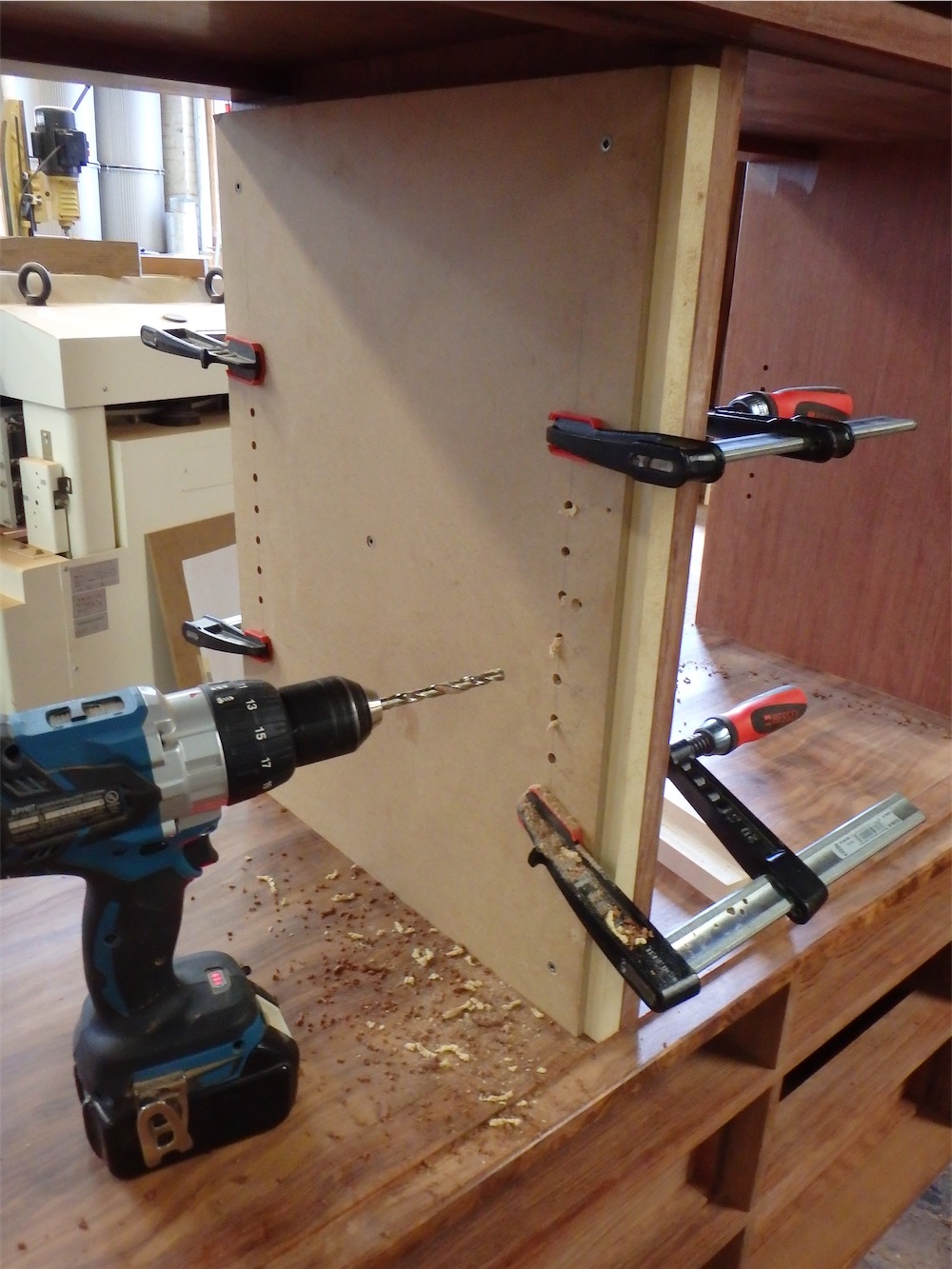
The jig is then clamped to the cabinet carcase like this:

A secondary block, also drilled on the mill, serves to control the depth of the hole. One doesn’t want any errant drill-throughs of the cabinet carcase at this sage, or any stage for that matter.
The holes are drilled and this is the result on that side panel:

The jig is then switched over to the opposite side of the cabinet:

Once both side panels of both cabinets are done, one layer of the drilling jig is removed so it can align properly to the central divider:
The central divider holes are drilled through from one side only, so back up blocks are required to preclude blow-out:

The completed through-holes in the middle divider of one cabinet:

It is worth noting, perhaps, that the design thickness of the central vertical divider, worked out many months ago, was in fact based upon accommodating the length of these pin inserts. It would have been all to easy to simply consider the divider thickness as an aesthetic matter only, and made it, say, 0.625" thick instead of 0.75" thick, however the shelf pin insert controlled this aspect of design. The important thing, I guess, is to see such issue aheads of time, rather than dealing with the repercussions of the oversight of such a seemingly minor item later on.
Once all the holes are done, the 7mm shelf pins can be fitted. I like to use the Lee Valley product, sourced from Italy, which has threaded inserts for each pin. The inserts are fitted using a special tool (no longer available in the 4mm size from LV for some unknown reason):

The instructions specify that the holes be 6.75mm if in softwood, and 7mm if in hardwood. Since the inserts themselves are 7mm in diameter, I thought drilling a 7mm hole would be a bad idea. An interference fit of some sort is desirable, after all. I looked through my drill index set and chose a letter drill, size ‘I’, which measures 0.272" (6.9mm) nominally. I measured it with my calipers and found it to be a hair under spec, at 6.85mm, which seemed like the perfect size. I confirmed such by drilling a hole in a block of bubinga and seeing how an insert fitted. All good. Letter size 'I’ it would be.
At that hole size, I found the insert could be pressed with the tool most of the way in by hand, the last 10~20% of travel requiring a tap of two with a hammer. Here’s the first insert in place:

The tool places the insert just below the wood surface. After all the inserts were in place, I found myself short by 8 inserts, a result of the design change in terms of the number of shelves and shelf hole positions. Another thing I now need to order from Lee Valley.
The back of the shelves required notching at the back on the outsides where the backing strips were located:

I elected to notch the undersurface of the shelf panels so as to house the pins in the shelf, rather than having the shelf sit atop the shelf pins. The reasoning here is that the housings around the pins trap the panel in place forward and back, precluding the chance that the panel could accidentally slide forward and drop down.
I put together a simple jig to rout the notches:

One side is set up so as to rout a narrow notch, for the rearmost pins, and the other side is routed with an elongated notch to accommodate any differences in seasonal movement between the panel and the cabinet carcase:

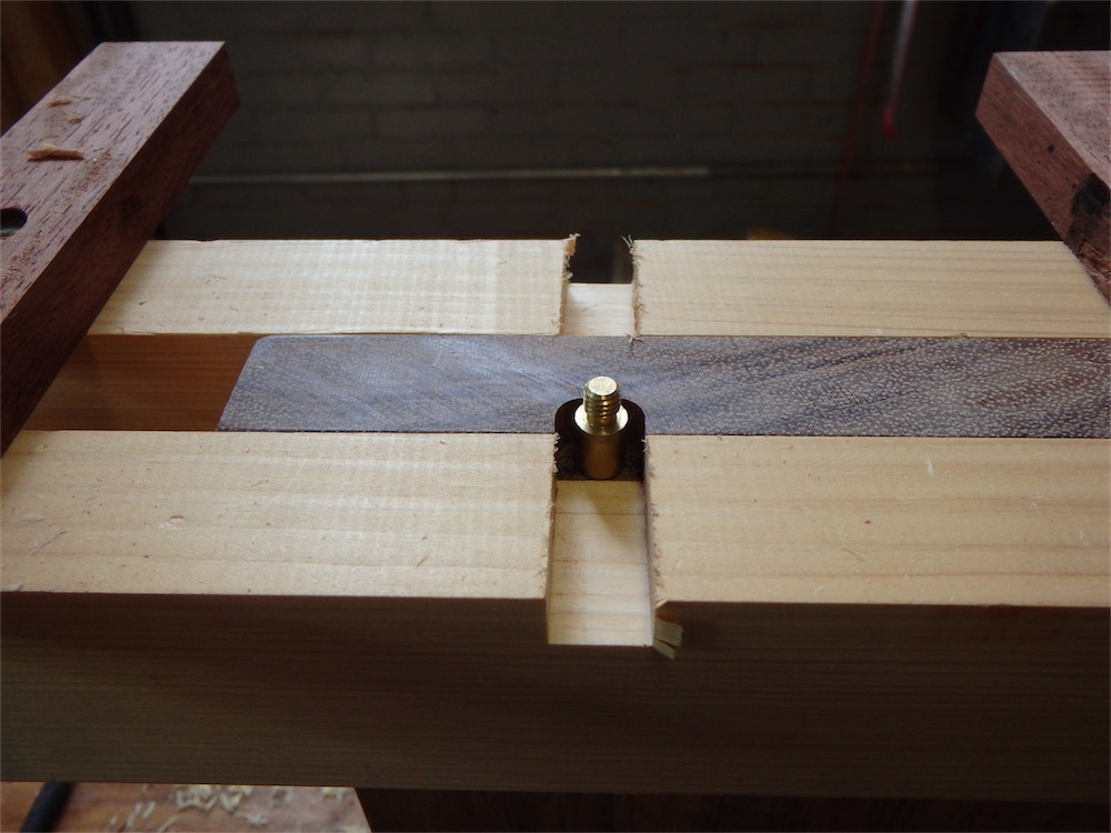
The rear notch with a pin in place to show the fit:

I used an 8mm spiral carbide bit, which I thought was close to the right size for a 7mm pin.
And here’s the elongated notch:
The reason to use two sizes of notch is that the shelf panel can be held to the rear, where it will meet the rear infill panel, and not open up any gap if the panel were to shrink - all movement happens at the front.
Here’s a look at the installed shelf atop the two pins:


A final task was to chamfer the front edges of the shelves:
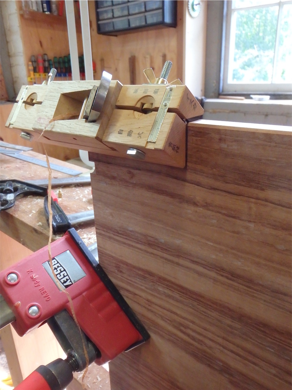
The upper arris is chamfered 45˚, while the lower arris is given a 3-4-5 triangle bevel (36.869˚) using a specialized plane for such a task:

The 'Isuka’ plane. The one seen above is a higher class type with ebony rubbing strips, a detachable sliding blade-holding body, full length brass insert in the sole, and a slightly skewed blade.
Once the pins were fitted to one cabinet, I could fit the shelves:

Another view - both cabinets this time:

The shelves are a full 17.5 inches (444.5mm) in depth, and are generously thick at 0.8125" (20.6mm). The shelves may see a lot of loaded weight, and I don’t want them to sag. I will be notching the shelves to sit over the pins, and have a bit of chamfering to do on the lead edges. Otherwise, they are ready to finish.
You may notice also from the above pair of photos that work on the bonnet portion of the cabinets is now underway. That will likely form the focus of the next post in this series.
Thanks for visiting.
via Tumblr http://davidpires578.tumblr.com/post/149143292764
No comments:
Post a Comment